We’re finally talking about them!
You were probably getting sick of me saying stuff like “we’ll get to that when we talk about buffers”. Well now’s the time to finally talk about buffers, but first…
你可能已经厌倦了我说的那些话,比如”当我们谈论缓冲区的时候,我们会说到那个”。现在是时候讨论缓冲区了,但是首先。。。
What is a buffer?
A buffer is a blob of data on the GPU. A buffer is guaranteed to be contiguous, meaning that all the data is stored sequentially in memory. Buffers are generally used to store simple things like structs or arrays, but it can store more complex stuff such as graph structures like trees (provided all the nodes are stored together and don’t reference anything outside of the buffer). We are going to use buffers a lot, so let’s get started with two of the most important ones: the vertex buffer, and the index buffer.
缓冲区是GPU上的一团数据。缓冲区保证是连续的,这意味着所有数据都按顺序存储在内存中。缓冲区通常用于存储简单的东西,如结构或数组,但它可以存储更复杂的东西,如树等图形结构(前提是所有节点都存储在一起,并且不引用缓冲区之外的任何内容)。我们将大量使用缓冲区,因此让我们从两个最重要的缓冲区开始:顶点缓冲区和索引缓冲区。
The vertex buffer
Previously we’ve stored vertex data directly in the vertex shader. While that worked fine to get our bootstraps on, it simply won’t do for the long-term. The types of objects we need to draw will vary in size, and recompiling the shader whenever we need to update the model would massively slow down our program. Instead we are going to use buffers to store the vertex data we want to draw. Before we do that though we need to describe what a vertex looks like. We’ll do this by creating a new struct.
之前,我们将顶点数据直接存储在顶点着色器中。虽然这样做可以很好地启动我们的引导系统,但从长远来看,这样做是行不通的。我们需要绘制的对象类型在大小上会有所不同,每当我们需要更新模型时重新编译着色器将大大降低我们的程序速度。相反,我们将使用缓冲区来存储要绘制的顶点数据。在我们这样做之前,我们需要描述一个顶点是什么样子的。我们将通过创建一个新的结构来实现这一点。
1 | // main.rs |
Our vertices will all have a position and a color. The position represents the x, y, and z of the vertex in 3d space. The color is the red, green, and blue values for the vertex. We need the Vertex to be copyable so we can create a buffer with it.
我们的顶点都有一个位置和颜色。该位置表示三维空间中顶点的x、y和z。颜色是顶点的红色、绿色和蓝色值。我们需要顶点是可复制的,这样我们就可以用它创建一个缓冲区。
Next we need the actual data that will make up our triangle. Below Vertex add the following.
接下来,我们需要组成三角形的实际数据。在顶点下方添加以下内容。
1 | //main.rs |
We arrange the vertices in counter clockwise order: top, bottom left, bottom right. We do it this way partially out of tradition, but mostly because we specified in the rasterization_state of the render_pipeline that we want the front_face of our triangle to be wgpu::FrontFace::Ccw so that we cull the back face. This means that any triangle that should be facing us should have its vertices in counter clockwise order.
我们按逆时针顺序排列顶点:顶部、左下角、右下角。我们这样做部分是出于传统,但主要是因为我们在渲染管道的光栅化状态中指定,我们希望三角形的前表面为wgpu::FrontFace::Ccw,以便剔除后表面。这意味着任何面向我们的三角形的顶点都应该按逆时针顺序排列。
Now that we have our vertex data, we need to store it in a buffer. Let’s add a vertex_buffer field to State.
现在我们有了顶点数据,我们需要将其存储在缓冲区中。让我们向State添加一个顶点vertex_buffer字段。
1 | // main.rs |
Now let’s create the buffer in new().
现在让我们在new()中创建缓冲区。
1 | // new() |
To access the create_buffer_init method on wgpu::Device we’ll have to import the DeviceExt extension trait. For more information on extension traits, check out this article.
要访问wgpu::Device上的create_buffer_init方法,我们必须导入DeviceExt扩展特性。有关扩展特性的更多信息,请参阅本文。
To import the extension trait, this line somewhere near the top of main.rs.
要导入扩展特性,请在main.rs顶部附近的某个位置输入如下代码。
1 | use wgpu::util::DeviceExt; |
You’ll note that we’re using bytemuck to cast our VERTICES as a &[u8]. The create_buffer_init() method expects a &[u8], and bytemuck::cast_slice does that for us. Add the following to your Cargo.toml.
您会注意到,我们使用bytemuck将顶点转换为&[u8]。create_buffer_init()方法需要一个&[u8],而bytemuck::cast_slice则为我们这样做。将以下内容添加到Cargo.toml中。
1 | bytemuck = { version = "1.4", features = [ "derive" ] } |
We’re also going to need to implement two traits to get bytemuck to work. These are bytemuck::Pod and bytemuck::Zeroable. Pod indicates that our Vertex is “Plain Old Data”, and thus can be interpretted as a &[u8]. Zeroable indicates that we can use std::mem::zeroed(). We can modify our Vertex struct to derive these methods.
为了让bytemuck发挥作用,我们还需要实现两个特性。它们是bytemuck::Pod和bytemuck::Zeroable。Pod表示我们的顶点是“普通的旧数据”,因此可以解释为a&[u8]。Zeroable表示我们可以使用std::mem::zeroed()。我们可以修改顶点结构来派生这些方法。
1 |
|
If your struct includes types that don’t implement Pod and Zeroable, you’ll need to implement these traits manually. These traits don’t require us to implement any methods, so we just need to use the following to get our code to work.
如果您的结构包含未实现Pod和Zeroable的类型,则需要手动实现这些特性。这些特性不需要我们实现任何方法,所以我们只需要使用以下方法来让代码正常工作。
1 | unsafe impl bytemuck::Pod for Vertex {} |
Finally we can add our vertex_buffer to our State struct.
最后,我们可以将顶点缓冲区添加到结构体State中。
1 | Self { |
So what do I do with it?
We need to tell the render_pipeline to use this buffer when we are drawing, but first we need to tell the render_pipeline how to read the buffer. We do this using VertexBufferLayouts and the vertex_buffers field that I promised we’d talk about when we created the render_pipeline.
我们需要告诉render_pipeline在绘图时使用此缓冲区,但首先我们需要告诉render_pipeline如何读取缓冲区。我们使用VertexBufferLayouts和vertex_buffers字段来实现这一点,我在创建render_pipeline时承诺过要讨论这个字段。
A VertexBufferLayout defines how a buffer is layed out in memory. Without this, the render_pipeline has no idea how to map the buffer in the shader. Here’s what the descriptor for a buffer full of Vertex would look like.
VertexBufferLayout定义缓冲区在内存中的布局方式。如果没有此选项,渲染管道将不知道如何映射着色器中的缓冲区。下面是一个充满顶点的缓冲区的描述符。
1 | wgpu::VertexBufferLayout { |
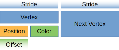
- The array_stride defines how wide a vertex is. When the shader goes to read the next vertex, it will skip over array_stride number of bytes. In our case, array_stride will probably be 24 bytes.
- step_mode tells the pipeline how often it should move to the next vertex. This seems redundant in our case, but we can specify wgpu::InputStepMode::Instance if we only want to change vertices when we start drawing a new instance. We’ll cover instancing in a later tutorial.
- Vertex attributes describe the individual parts of the vertex. Generally this is a 1:1 mapping with a struct’s fields, which it is in our case.
- This defines the offset in bytes that this attribute starts. The first attribute is usually zero, and any future attributes are the collective size_of the previous attributes data.
- This tells the shader what location to store this attribute at. For example layout(location=0) in vec3 x in the vertex shader would correspond to the position field of the struct, while layout(location=1) in vec3 x would be the color field.
- format tells the shader the shape of the attribute. Float3 corresponds to vec3 in shader code. The max value we can store in an attribute is Float4 (Uint4, and Int4 work as well). We’ll keep this in mind for when we have to store things that are bigger than Float4.
- array_stride定义顶点的宽度。当着色器读取下一个顶点时,它将跳过数组的字节数。在我们的例子中,数组的步长可能是24字节。
- step_mode告诉管道它应该移动到下一个顶点的频率。在我们的例子中,这似乎是多余的,但如果我们只想在开始绘制新实例时更改顶点,则可以指定wgpu::InputStepMode::Instance。我们将在后面的教程中介绍实例化。
- 顶点属性描述顶点的各个部分。通常,这是一个1:1映射,带有结构的字段,在我们的例子中就是这样。
- 这定义了该属性开始的偏移量(以字节为单位)。第一个属性通常为零,任何未来属性都是前一个属性数据的集合大小。
- 这将告知着色器存储此属性的位置。例如,顶点着色器中vec3 x中的布局(位置=0)将对应于结构的位置字段,而vec3 x中的布局(位置=1)将对应于颜色字段。
- format告诉着色器属性的布局。Float3对应于着色器代码中的vec3。我们可以存储在属性中的最大值是Float4(Uint4和Int4也可以使用)。当我们必须存储比Float4大的东西时,我们会注意这一点。
For you visually learners, our vertex buffer looks like this.
对于您来说,我们的顶点缓冲区如下所示。

Let’s create a static method on Vertex that returns this descriptor.
让我们在顶点上创建一个静态方法,返回这个描述符。
1 | // main.rs |
Specifying the attributes as we did now is quite verbose. We could use the vertex_attr_array macro provided by wgpu to clean things up a bit. With it our VertexBufferLayout becomes
像我们现在这样指定属性是相当冗长的。我们可以使用wgpu提供的vertex_attr_array宏稍微清理一下。有了它,我们的VertexBuffer布局变得
1 | wgpu::VertexBufferLayout { |
While this is definitely nice, we would have to change the lifetime on wgpu::VertexBufferLayout to ‘static as rust wouldn’t compile the code because the result of vertex_attr_array is a temporary value, which we can’t return from a function.
虽然这确实很好,但我们必须将wgpu::VertexBufferLayout上的生存期更改为“静态”,因为rust不会编译代码,因为vertex_attr_array数组的结果是一个临时值,我们无法从函数返回。
Beyond that, I feel it’s good to show how the data gets mapped, so I’ll forgo using this macro for now.
除此之外,我觉得展示数据是如何映射的很好,所以我现在放弃使用这个宏。
Now we can use it when we create the render_pipeline.
现在,我们可以在创建render_pipeline时使用它。
1 | let render_pipeline = device.create_render_pipeline(&wgpu::RenderPipelineDescriptor { |
One more thing: we need to actually set the vertex buffer in the render method otherwise our program will crash.
还有一件事:我们需要在渲染方法中实际设置顶点缓冲区,否则我们的程序将崩溃。
1 | // render() |
set_vertex_buffer takes two parameters. The first is what buffer slot to use for this vertex buffer. You can have multiple vertex buffers set at a time.
set_vertex_buffer采用两个参数。第一个是用于此顶点缓冲区的缓冲槽。一次可以设置多个顶点缓冲区。
The second parameter is the slice of the buffer to use. You can store as many objects in a buffer as your hardware allows, so slice allows us to specify which portion of the buffer to use. We use .. to specify the entire buffer.
第二个参数是要使用的缓冲区的切片。在硬件允许的情况下,可以在缓冲区中存储任意多的对象,因此slice允许我们指定要使用的缓冲区部分。我们用..指定整个缓冲区。
Before we continue, we should change the render_pass.draw() call to use the number of vertices specified by VERTICES. Add a num_vertices to State, and set it to be equal to VERTICES.len().
在继续之前,我们应该更改render_pass.draw()调用以使用顶点指定的顶点数。将num_vertices添加到状态,并将其设置为等于VERTICES.len()。
1 | // main.rs |
Then use it in the draw call.
1 | // render |
Before our changes will have any effect, we need to update our vertex shader to get its data from the vertex buffer. We’ll also have it include the vertex color as well.
在更改产生任何效果之前,我们需要更新顶点着色器以从顶点缓冲区获取其数据。我们还将让它包括顶点颜色。
1 | // Vertex shader |
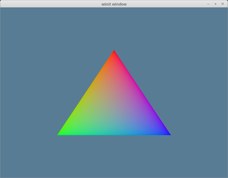
If you’ve done things correctly, you should see a triangle that looks something like this.
如果你做的正确,你应该看到一个三角形,看起来像这样。

The index buffer
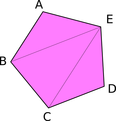
We technically don’t need an index buffer, but they still are plenty useful. An index buffer comes into play when we start using models with a lot of triangles. Consider this pentagon.
从技术上讲,我们不需要索引缓冲区,但它们仍然非常有用。当我们开始使用带有大量三角形的模型时,索引缓冲区就开始发挥作用。考虑一下这个五角大厦。

It has a total of 5 vertices, and 3 triangles. Now if we wanted to display something like this using just vertices we would need something like the following.
它总共有5个顶点和3个三角形。现在,如果我们只想用顶点来显示这样的东西,我们需要下面这样的东西。
1 | const VERTICES: &[Vertex] = &[ |
You’ll note though that some of the vertices are used more than once. C, and B get used twice, and E is repeated 3 times. Assuming that each float is 4 bytes, then that means of the 216 bytes we use for VERTICES, 96 of them are duplicate data. Wouldn’t it be nice if we could list these vertices once? Well we can! That’s were an index buffer comes into play.
但您会注意到,有些顶点被多次使用。C、 B使用两次,E重复三次。假设每个浮点是4个字节,那么这意味着我们用于顶点的216个字节中,有96个是重复数据。如果我们能列出这些顶点一次,不是很好吗?我们可以!这就是索引缓冲区发挥作用的原因。
Basically we store all the unique vertices in VERTICES and we create another buffer that stores indices to elements in VERTICES to create the triangles. Here’s an example of that with our pentagon.
基本上,我们将所有唯一的顶点存储在VERTICES中,并创建另一个缓冲区来存储顶点中元素的索引以创建三角形。这是我们五角大楼的一个例子。
1 | // main.rs |
Now with this setup our VERTICES take up about 120 bytes and INDICES is just 18 bytes given that u16 is 2 bytes wide. We add 2 bytes padding as wgpu requires buffers to be aligned to 4 bytes. All together our pentagon is 134 bytes in total. That means we saved 82 bytes! It may not seem like much, but when dealing with tri counts in the hundreds of thousands, indexing saves a lot of memory.
现在,在这个设置中,我们的顶点占用了大约120个字节,而索引仅为18个字节,因为u16的宽度为2个字节。我们添加了2个字节的填充,因为wgpu要求缓冲区与4个字节对齐。我们的五角大楼总共有134字节。这意味着我们节省了82字节!它可能看起来不太多,但在处理数十万的三重计数时,索引可以节省大量内存。
There’s a couple of things we need to change in order to use indexing. The first is we need to create a buffer to store the indices. In State’s new() method create the index_buffer after you create the vertex_buffer. Also change num_vertices to num_indices and set it equal to INDICES.len().
为了使用索引,我们需要改变一些事情。首先,我们需要创建一个缓冲区来存储索引。在State的new()方法中,在创建顶点缓冲区之后创建索引缓冲区。还可以将num_vertices更改为num_indices,并将其设置为INDICES.len()。
1 | let vertex_buffer = device.create_buffer_init( |
We don’t need to implement Pod and Zeroable for our indices, because bytemuck has already implemented them for basic types such as u16. That means we can just add index_buffer and num_indices to the State struct.
我们不需要为索引实现Pod和Zeroable,因为bytemuck已经为u16等基本类型实现了它们。这意味着我们可以将index_buffer和num_indices添加到State结构中。
1 | struct State { |
And then populate these fields in the constructor:
然后在构造函数中填充这些字段:
1 | Self { |
All we have to do now is update the render() method to use the index_buffer.
我们现在要做的就是更新render()方法以使用index_buffer。
1 | // render() |
A couple things to note:
- The method name is set_index_buffer not set_index_buffers. You can only have one index buffer set at a time.
- When using an index buffer, you need to use draw_indexed. The draw method ignores the index buffer. Also make sure you use the number of indices (num_indices), not vertices as your model will either draw wrong, or the method will panic because there are not enough indices.
有几件事需要注意:
- 方法名称是set_index_buffer而不是set_index_buffers。一次只能设置一个索引缓冲区。
- 使用索引缓冲区时,需要使用draw_indexed。draw方法忽略索引缓冲区。还要确保使用的是索引的数量(num_index),而不是顶点,否则您的模型可能会绘制错误,或者该方法会因为索引不足而死机。
With all that you should have a garishly magenta pentagon in your window.
所有这些,你应该有一个华丽的洋红色五角大楼在你的窗口。
Color Correction
If you use a color picker on the magenta pentagon, you’ll get a hex value of #BC00BC. If you convert this to RGB values you’ll get (188, 0, 188). Dividing these values by 255 to get them into the [0, 1] range we get roughly (0.737254902, 0, 0.737254902). This is not the same as we are using for our vertex colors which is (0.5, 0.0, 0.5). The reason for this has to do with color spaces.
如果在洋红五角大楼上使用颜色选择器,将得到十六进制值#BC00BC。如果您将其转换为RGB值,您将得到(188,0188)。将这些值除以255得到[0,1]范围,我们大致得到(0.737254902,0,0.737254902)。这与我们使用的顶点颜色(0.5、0.0、0.5)不同。这与颜色空间有关。
Most monitors use a color space know as sRGB. Our swap chain is (most likely depending on what is returned from adapter.get_swap_chain_preferred_format()) using an sRGB texture format. The sRGB format stores colors according to their relative brightness instead of their actual brightness. The reason for this is that our eyes don’t perceive light linearly. We notice more differences in darker colors than we do lighter colors.
大多数显示器使用的颜色空间称为sRGB。我们的swap chain是(很可能取决于适配器返回的内容。adapter.get_swap_chain_preferred_format())使用sRGB纹理格式。sRGB格式根据颜色的相对亮度而不是实际亮度存储颜色。原因是我们的眼睛不能线性感知光线。我们注意到深色的差异比浅色的多。
You get an approximation of the correct color using the following formula: srgb_color = (rgb_color / 255) ^ 2.2. Doing this with an RGB value of (188, 0, 188) will give us (0.511397819, 0.0, 0.511397819). A little off from our (0.5, 0.0, 0.5). While you could tweak the formula to get the desired values, you’ll likely save a lot of time by using textures instead as they are stored as sRGB by default, so they don’t suffer from the same color inaccuracies that vertex colors do. We’ll cover textures in the next lesson.
使用以下公式可以获得正确颜色的近似值:srgb_color=(rgb_color/255)^2.2。在RGB值为(188,0188)的情况下执行此操作将得到(0.511397819,0.0,0.511397819)。离我们的(0.5,0.0,0.5)有点远。虽然可以调整公式以获得所需的值,但使用纹理可能会节省大量时间,因为默认情况下纹理存储为sRGB,因此它们不会像顶点颜色那样出现颜色不准确的情况。我们将在下一课中介绍纹理。
Challenge
Create a more complex shape than the one we made (aka. more than three triangles) using a vertex buffer and an index buffer. Toggle between the two with the space key.
创建一个比我们制作的形状更复杂的形状(aka。三个以上的三角形)使用顶点缓冲区和索引缓冲区。使用空格键在两者之间切换。